Powerful Naval Architecture Software
Create initial hull designs and assess stability of all types of existing marine vessels. Use this complete set of integrated naval architecture tools to visualize and optimize vessel designs.
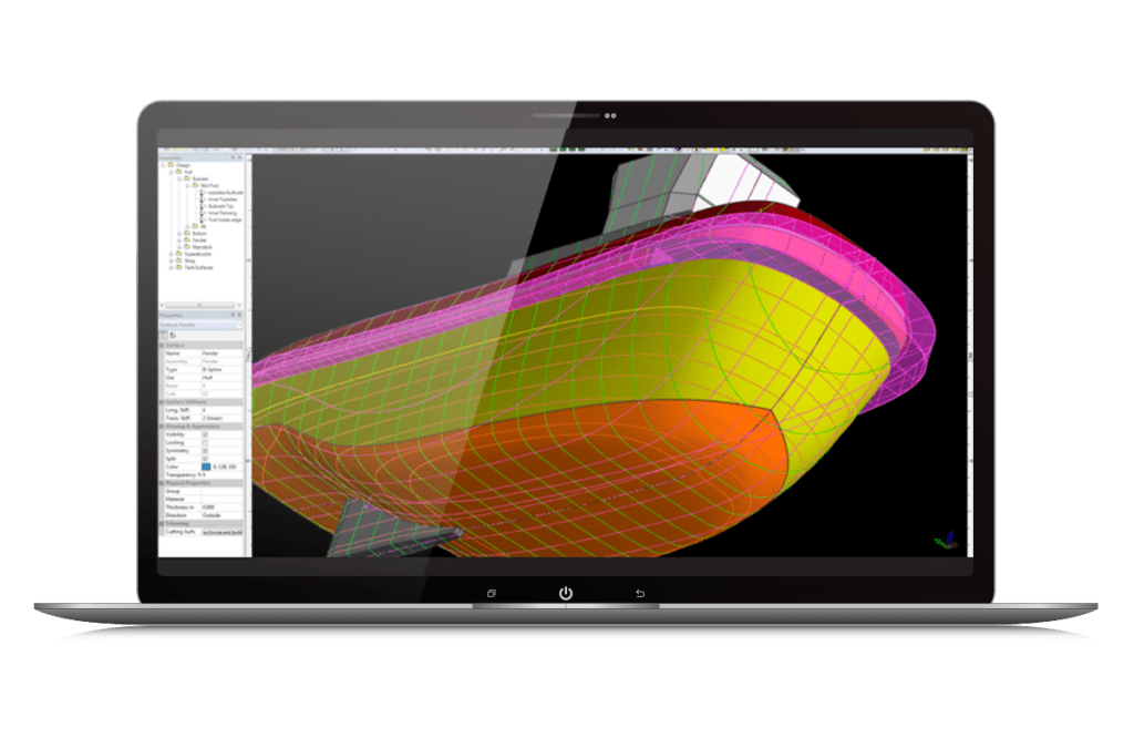
What is MAXSURF?
Maxsurf is naval architecture software ideal for the design of marine vessels. Maxsurf includes capabilities for hull modeling, stability, motions and resistance prediction, structural modeling, structural analysis, and export to vessel detailing. Maxsurf operates from a single parametric 3D model in order to ensure smooth communication and coordination across various involved in the project.
Assess Vessel Compliance
Ensure compliance with international stability criteria and balance vessel performance requirements using integrated analysis tools. Perform a range of analyses including intact and damaged stability, resistance and motions prediction, and structural analysis.
Model Marine Vessels
Create complex 3D hull forms for any type of vessel using wizards and interactive sketch tools. Systematically explore design alternatives by making measured changes to models with easy-to-use tools. Apply transformations to increase the productivity of the initial hull design process.
Optimize Vessel Design
Perform faster hull form variation and analysis with team-based concurrent modeling on a common 3D parametric model. Easily visualize and assess design alternatives within a consistent graphical environment with smooth data flow.
Maxsurf
- Model complex vessels using dynamically trimmed 3D NURB surfaces
- Flexible data import, mesh modeling, and automatic curve and surface fitting
- Design power, sail, commercial, and naval vessels made from steel, aluminum, wood, or composite materials
- Probabilistic damage stability
- Radiation diffraction panel method motions prediction
- Dynamic, time domain, and structural analysis
*Prices vary per region. For more options, see licensing and subscriptions section.
User Quote
“Using the Maxsurf software, the time required to accurately determine the stability characteristics of the vessel was reduced from a projected three months to one month.”
– Design Team, Incat Crowther
FEATURED USER STORIES
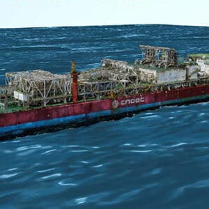
Offshore Oil Operations
3D Reality Modeling for Offshore
The use of Bentley’s integrated technology created a reality mesh of an FPSO platform, saving CNY 1 million.

Offshore WInd Farm
3D Construction modeling
Shanghai Investigation, Design, & Research Institute saved big with 3D modeling for the first anti-ice cones.
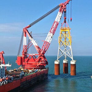
Resilient foundation
Wind Turbine Resists Typhoons
PLAXIS and SACS provided a unified environment to simultaneously create models and test soil interactions.
Maxsurf Software Resources
Frequently Asked Questions
Maxsurf offers comprehensive capabilities for the design of all types of marine vessels. Maxsurf includes capabilities for hull modeling, stability, motions and resistance prediction, structural modeling, structural analysis, and export to vessel detailing. Maxsurf applications operate from a single parametric 3D model that facilitates smooth communication and coordination among different team members and design activities.
Maxsurf is based on industry-standard NURB surface modeling. It reads and writes DGN, 3DM, IGES, and DXF files, which facilitate a smooth data transfer with MicroStation, Rhino, AutoCAD, ShipConstructor, and SolidWorks. It also features copy and paste to and from Microsoft Excel, and a full automation interface, compatible with Microsoft Excel and Microsoft Word, that allows macros to be used to control Maxsurf for optimization studies or customized calculation and reporting.
The price of Maxsurf varies per region. While there are various types of licensing available, a common choice is the 12-month practitioner license offered through Bentley’s eStore. When you purchase through the eStore you get a Virtuoso Subscription which means you get both the software AND the training, expert services, and custom mentoring you need to get started quickly.
Processor
CPU: Pentium 4 or higher
Operating System
Windows 8/8.1, 10, 11
Memory
RAM: Minimum 2 GB–SACS performance is dependent on model size and resources available
Hard Disk
Minimum 10 GB partition for SACS installation recommended
Display
Graphics card with a chipset that supports Open GL
Network
A network connection is required. 100 Base-T or greater local area ethernet network TCP/IP network protocol is supported
For the most up-to-date system requirements, visit Bentley Communities.
Licensing and Subscription options
Choose What is Right for You
One-year license with training
Virtuoso Subscription – A popular choice for small and medium-sized businesses
Get access to software that comes with training – fast! Bentley’s eStore, Virtuosity, offers a convenient way to lease a 12-month license of Bentley software for a low, upfront cost. Every online purchase through Virtuosity comes as a Virtuoso Subscription that includes training and auto-renewals.
With no contract required, it’s easy to get started quickly.
One-time purchase with support
Perpetual License with SELECT
A perpetual license of Bentley software is a one-time purchase, with a yearly maintenance subscription, called SELECT. This includes 24/7/365 technical support, learning resources, and the ability to exchange licenses for other software once a year. With SELECT, you will benefit from:
- License pooling, so you can access your software from multiple computers.
- Access additional Bentley software with Term Licenses, which allow you to pay for what you use without the upfront cost of purchasing a perpetual license.
Annual renewal quotes are delivered directly to your inbox, and our experienced Renewal Representatives are available to answer your questions and guide you through any changes you’d like to make.
Enterprise Organizations
We’ve got your back
For larger organizations with in-depth requirements, we offer plans to provide global pricing and access to our comprehensive portfolio of solutions and success plan services. Contact us about how to get access to software, global best practices, implementation services, training, and technical support to help your organization realize its full potential while addressing your unique needs.
